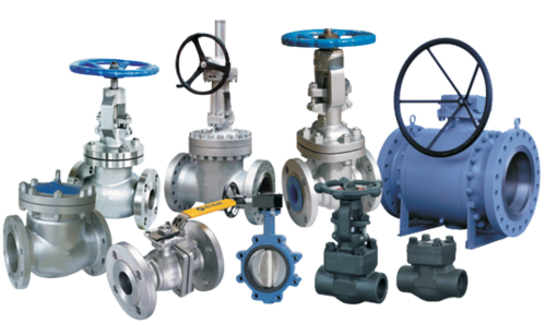
VALVES
VALVES
Valves on a pump control the flow of liquid through a pump. These help to regulate pressure within a pump and prevent against possible breakage. Any pump should have two valves attached; one at the inlet, or suction, and the other at the outlet, or discharge area.
Pump
A pump is a device that moves fluids (liquids or gases), or sometimes slurries, by mechanical action, typically converted from electrical energy into Hydraulic energy. ... Pumps operate by some mechanism (typically reciprocating or rotary), and consume energy to perform mechanical work moving the fluid.
Function
A pump produces liquid movement or flow: it does not generate pressure. It produces the flow necessary for the development of pressure which is a function of resistance to fluid flow in the system .
Pumps can be classified into three major groups according to the method they use to move the fluid: direct lift, displacement, and gravity pumps.
All pumps use basic forces of nature to move a liquid. As the moving pump part (impeller, vane, piston diaphragm,etc.) begins to move, air is pushed out of the way. The movement of air creates a partial vacuum (low pressure) which can be filled up by more air, or in the case of water pumps, water.
BUTTERFLY VALVE
A butterfly valve is from a family of valves called quarter-turn valves. In operation, the valve is fully open or closed when the disc is rotated a quarter turn. The "butterfly" is a metal disc mounted on a rod. When the valve is closed, the disc is turned so that it completely blocks off the passageway.
Function
The butterfly valve is a rotary valve in which a disk-shaped seating element is rotated 90° to open or close the flow passage. They are used in throttling service, particularly where large-size valves with automatic actuators are required. Butterfly valves cannot be used where a nonobstructed, full opening is needed.
Advantages
The disc is lighter than a ball, and the valve requires less structural support than a ball valve of comparable diameter. Butterfly valves are very precise, which makes them advantageous in industrial applications. They are quite reliable and require very little maintenance.They are small and, when actuated pneumatically, open and close very quickly.

GATE VALVE
How does gate valve work?
Gate valves work by inserting a rectangular gate or wedge into the path of a flowing fluid. They are operated by a threaded stem which connects the actuator (generally a hand wheel or motor) to the stem of the gate. If the valve has a rising stem its position can be seen just by looking at the position of the stem.
What are different types of gate valves?
Gate valves can be divided into two main types: Parallel and wedge-shaped. The parallel gate valves use a flat gate between two parallel seats, and a popular type is the knife gate valve designed with a sharp edge on the bottom of the gate.
Gate valves are designed for fully open or fully closed service. They are installed in pipelines as isolating valves, and should not be used as control or regulating valves. Operation of a gate valve is performed doing an either clockwise to close (CTC) or clockwise to open (CTO) rotating motion of the stem.
A gate valve, also known as a sluice valve, is a valve that opens by lifting a barrier (gate) out of the path of the fluid. Gate valves require very little space along the pipe axis and hardly restrict the flow of fluid when the gate is fully opened.
Blood the main advantage of gate valve include:
The fluid resistance of the valve is small. Because the valve body of the gate valve is the straight-through type and the flow of the medium doesn't change direction, the fluid resistance of it is small compared with other kinds of valves.
The sealing performance is better than that of the shut-off valve. The opening and closing of it are more convenient than those of the shut-off valve.
The range of applications is wide. In addition to steam, oil and other media, it can be used in medium containing granular solid and with large viscosity. It can also be used as a venting valve and a low vacuum system valve.
A gate valve is a valve that has dual flow directions. It’s not subject to the flow directions of the medium. Therefore, it is suitable for use in the pipeline where the medium may change the flow direction. It is also easy to install.
Advantages of Using Gate Valves
- It offers small fluid resistance as the inner media channel of the body is straight.
- It is an energy-efficient alternative as it consumes less power while opening or closing. This is because the movement direction lies perpendicular to the media flow direction. Hence, as compared to globe valves, gate valves save both energy and time.
- Gate valves offer an unobstructed media flow from any direction of the valve body. It does not decrease pressure which makes it suitable for pipeline where the flow direction may change.
Advantages of Using Gate Valves
- It offers small fluid resistance as the inner media channel of the body is straight. It flows though the valve which does not hampers the direction of the flow.
- It is an energy-efficient alternative as it consumes less power while opening or closing.
- Gate valves offer an unobstructed media flow from any direction of the valve body.
- The overall structure length of gate valves is shorter than globe valves. The valve clack aligns with the valve body, thus making the structure length of gate valves shorter than globe valves.
- The seal functioning is quite good thus, making it less eroded while it is open.
- As compared to globe valves, the erosion of sealing surface is lighter.
- The valve body is simple and easy to operate. It features a good casting process which offers a wide range.
Advantages of Using Gate Valves
Gate valves are widely used for all types of applications and are suitable for both above-ground and underground installation. Not least for underground installations it is paramount to choose the right type of valve to avoid high replacement costs.
Gate valves are designed for fully open or fully closed service. They are installed in pipelines as isolating valves, and should not be used as control or regulating valves. Operation of a gate valve is performed doing an either clockwise to close (CTC) or clockwise to open (CTO) rotating motion of the stem. When operating the valve stem, the gate moves up- or downwards on the threaded part of the stem.
Gate valves are often used when minimum pressure loss and a free bore is needed. When fully open, a typical gate valve has no obstruction in the flow path resulting in a very low pressure loss, and this design makes it possible to use a pipe-cleaning pig. A gate valve is a multiturn valve meaning that the operation of the valve is done by means of a threaded stem. As the valve has to turn multiple times to go from open to closed position, the slow operation also prevents water hammer effects.
Gate valves can be used for a vast number of fluids. AVK's gate valves are suitable under the following working conditions:
- Potable water, wastewater and neutral liquids: temperature between -20 and +70 °C, maximum 5 m/s flow velocity and up to 16 bar differential pressure.
- Gas: temperature between -20 and +60 °C, maximum 20 m/s flow velocity and up to 16 bar differential pressure.
See AVK’s installation and maintenance instruction for water/wastewater and gas.

BALL VALVE
A ball valve is a form of quarter-turn valve which uses a hollow, perforated and pivoting ball to control flow through it. It is open when the ball's hole is in line with the flow and closed when it is pivoted 90-degrees by the valve handle.[1] The handle lies flat in alignment with the flow when open, and is perpendicular to it when closed, making for easy visual confirmation of the valve's status.[2] The shut position 1/4 turn could be in either CW or CCW direction. (S = SHUT, O = OPEN)
Ball valves are durable, performing well after many cycles, and reliable, closing securely even after long periods of disuse. These qualities make them an excellent choice for shutoff and control applications, where they are often preferred to gates and globe valves, but they lack their fine control in throttling applications.
The ball valve's ease of operation, repair, and versatility lend it to extensive industrial use, supporting pressures up to 1,000 bar (100 MPa; 15,000 psi) and temperatures up to 752 °F (400 °C), depending on design and materials used. Sizes typically range from 0.2 to 48 inches (5.1 to 1,219.2 mm). Valve bodies are made of metal, plastic, or metal with a ceramic; floating balls are often chrome plated for durability. One disadvantage of a ball valve is that they trap water in the center cavity while in the closed position. In the event of a freeze, the sides can crack due to expansion of ice forming. Some means of insulation or heat tape in this situation will usually prevent damage. Another option for cold climates is the "freeze tolerant ball valve". This style of ball valve incorporates a freeze plug in the side so in the event of a freeze up, the freeze plug ruptures (acts as a sacrificial disk), thus making for an easy repair. Now instead of replacing the whole valve, just screw in a new freeze plug.
In the case that a ball valve is used for cryogenics or product that may expand inside of the ball, there is a vent drilled into the upstream side of the valve. This is referred to as a vented ball. Safety is the number one concern when engineers specify a vented ball.
A ball valve should not be confused with a "ball-check valve", a type of check valve that uses a solid ball to prevent undesired backflow.
Other types of quarter-turn valves include the butterfly valve and plug valve and freeze proof ball valve.
Types
There are five general body styles of ball valves: single body, three-piece body, split body, top entry, and welded. The difference is based on how the pieces of the valve—especially the casing that contains the ball itself—are manufactured and assembled. The valve operation is the same in each case.
In addition, there are different styles related to the bore of the ball mechanism itself. And depending on the working pressure, the ball valves are categorized as low pressure ball valves and high pressure ball valves. In most industries, the ball valves with working pressures higher than 3000 psi are considered as high pressure ball valves. Usually the max. working pressure for the high pressure ball valves is 7500 psi, and depends on the structure, sizes and sealing materials, the max. working pressure of high pressure ball valves can be up to 15000 psi. High pressure ball valves are mostly used in applications under high pressure such as hydraulic systems, so they are known as hydraulic ball valves also.
Ball valves in sizes up to 2 inch generally come in single piece, two or three piece designs. One piece ball valves are almost always reduced bore, are relatively inexpensive and generally are throw-away. Two piece ball valves are generally slightly reduced (or standard) bore, they can be either throw-away or repairable. The 3 piece design allows for the center part of the valve containing the ball, stem & seats to be easily removed from the pipeline. This facilitates efficient cleaning of deposited sediments, replacement of seats and gland packings, polishing out of small scratches on the ball, all this without removing the pipes from the valve body. The design concept of a three piece valve is for it to be repairable.
Ball Valve - How They Work
A ball valve is a shut off valve that controls the flow of a liquid or gas by means of a rotary ball having a bore. By rotating the ball a quarter turn (90 degrees) around its axis, the medium can flow through or is blocked. They are characterized by a long service life and provide a reliable sealing over the life span, even when the valve is not in use for a long time. As a result, they are more popular as a shut off valve then for example the gate valve. For a complete comparison, read our gate valve vs ball valve article. Moreover, they are more resistant against contaminated media than most other types of valves. In special versions, ball valves are also used as a control valve. This application is less common due to the relatively limited accuracy of controlling the flow rate in comparison with other types of control valves. However, the ball valve also offers some advantages here. For example, the valve still ensures a reliable sealing, even in the case of dirty media. Figure 1 shows a sectional view of a ball valve.
Advantages of ball valves:
- Efficiency: Ball valves don’t need any lubrication, and offer a bubble-tight seal with low torque.
- Affordability: They can often be purchased at a considerably lower cost than comparable products for the same job.
- Durability: They offer a long service life and, when used under the right conditions, will provide many years of reliable use. Ball valves are less prone to damage than other kinds of valves, and the plastic variety aren’t susceptible to corrosion.
- Easy to use: Ball valves are relatively quick and easy to install, and plastic ball valves are light and easy to handle.
- Versatile: They’re appropriate for a wide range of industrial applications where it’s necessary to regulate the flow of liquids or gases.
- Strong: Ball valves can maintain and regulate high pressure, high volume and a high flow of temperature.
- Simple to repair: Easily access the seats when a valve requires fixing.

SLUICE VALVE
What is sluice valve?
A large valve in which a rectangular or circular gate slides across the opening.
It has been used in oil tankers to permit gravity flow from tank to tank, with the valve being operated from the weather deck.